An automated test bench
for automotive gas injectors checkup
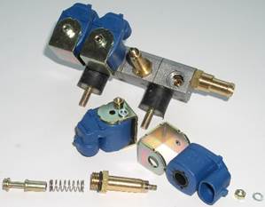
An electormagnetic gas
injector is the basic metering component of the 4-th generation automotive
gas-fuel system.
The identity of the
gas injectors determines most of the basic specifications of the vehicle,
running on gas: exhaust gases composition, dynamics, idle stability, gas fuel
consumption.
The open status time
of the gas injector on practice is not definitely
proportional to controlling electric impulse duration. The time additionally
depends upon many factors. Among these are: pressure drop on the injector, coil
inductance and active resistance, core mass, spring resistance, the gap between
the core and the seat, the injectors orientation (deviation from vertical) and
so on. The identity of these factors must be ensured by the technology. On
practice they differ from one injector to another. This results in the
dispersion of the behaviors of the injectors being used jointly. The dispersion
also depends upon the control impulse duration. That’s why the gas injectors behaviors comparison should be executed in
dynamics only and in the conditions under which the injectors work on the
engine. The basic conditions are
pressure drop presence and controlling electric impulses supply.
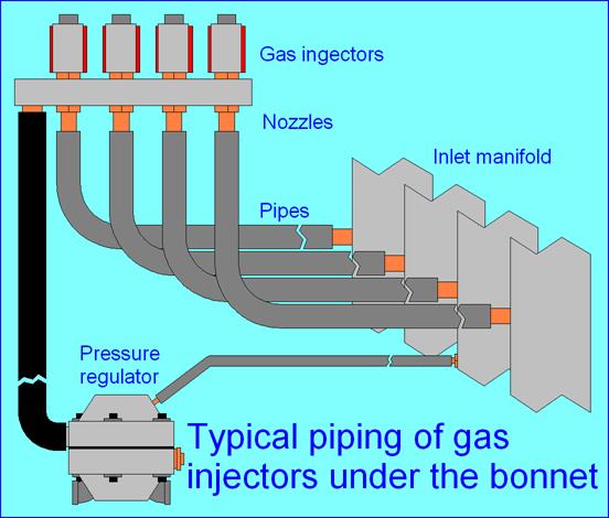
There are also some
more ‘external’ factors, that determine the injectors
behaviors. The basic are:
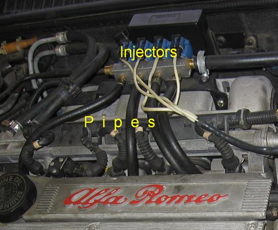
- the length, the
form and the cross section of the pipes that connect the injectors and the
inlet manifold;
- the angles
under witch the pipes are connected to the inlet
manifold;
- the flow areas
of the injectors outlet nozzles.
These ‘external’
factors differ in practice from injector to injector and from vehicle to
vehicle. That’s why the possibility is important to check the pneumatic routs
identities for each a cylinder on the way from pressure regulator to inlet
manifold. The gas injectors installed under the bonnet once are hardly
accessible after as a rule. It is difficult to extract them for checkup and to
install back then. So very desirable is the opportunity to checkup the
injectors without their extraction from under the bonnet. The defective
injector only can be extracted if detected and replaced or repaired.
So, it is obvious,
that compact, fast, highly productive, completely automatic, safety and
efficient equipment is needed to fairly check up the
vehicle gas injectors in every day work on auto-gas service.
The test bench is
meant to checkup automotive gas injectors both alone and directly on a vehicle.
During the checkup both safe gas and electric control impulses are supplied to
the injectors. The injectors run just as
under the bonnet and their supply characteristics are being directly measured
as gas consumption via electric impulse duration. The characteristics curves are displayed on
the computer monitor and compared automatically. The dispersion of the
characteristics is automatically calculated and also can be estimated visually
from the screen. Also can be estimated the linearity of the supply
characteristics and the control electric impulse minimal duration to open each
the injector.
There is ‘motor mode’
in the bench computer program. In the ‘motor mode’ the bench generates control
pulses for gas injectors in any desirable mode: sequential, synchronous,
coupled… In the ‘motor mode’
the ‘load’ and the ‘rotations’ can be delicately tuned via
computer program controls and the gas consumption is being continuously
measured. A professional can detect injectors
characteristics dispersion even orally in this mode: the sound of the injectors
that run under pressure is loud and very distinctive. The ‘motor mode’ can also
be used in educational purposes to demonstrate both the 4-th generation
automotive gas system and gas injectors functioning.
1. The bench checks normally closed
injectors (closed with no electric current in coils).
Coil resistance: 1 Ohm or more.
2. Working gas to be used – any safe and
non-aggressive gas:
-
compressed air;
-
compressed nitrogen;
-
evaporated carbon dioxide.
Electrical heater is present to use high input pressures and evaporated
carbon dioxide.
3. Input pressure:
-
at high pressure input: 10-200bar;
-
at low pressure input: 5-7bar with receiver volume
50liters or more and pressure maintaining system.
4. Pressure at the basic output: 1bar.
5. Pressure at the auxiliary output: up to
7bar.
6. Electric control pulses durations range:
1-25ms.
7. Checkup time for 4 injectors: 2.5min
(common mode); 6min (precise mode); 30min (high precision mode).
8. Sensitivity: 3 ranges
for weak, common and strong signals from injectors with various nozzles
diameters.
9. Power supply: 1.5A 220V AC.
10. Personal computer to be used:
-
windows XP;
-
USB port;
-
800X600 or better screen resolution.
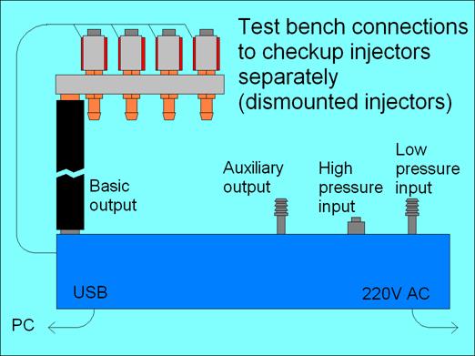
To test new injectors
or ones dismounted from a vehicle. The pipe from the basic output being long
enough, mounted injectors under the bonnet can also be checked with these
connections.
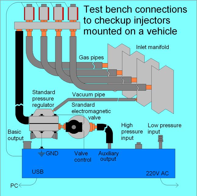
To checkup injectors,
mounted on a vehicle. Standard pressure regulator and standard gas supply valve,
mounted on the vehicle, are also used and so are also being checked:
1. Test bench inlets,
outlets and controls.
1 – heater LED;
2 – power ON LED;
3 – plug for injectors cable
connection;
4 – high pressure input;
5 – low pressure input plug;
6 – basic output;
7 – auxiliary output;
8 – power plug;
9 – USB port plug;
10 – plug for standard gas
valve control cable connection;
11 – standard gas valve plug
fuse;
12 – plug for vehicle ground connection.
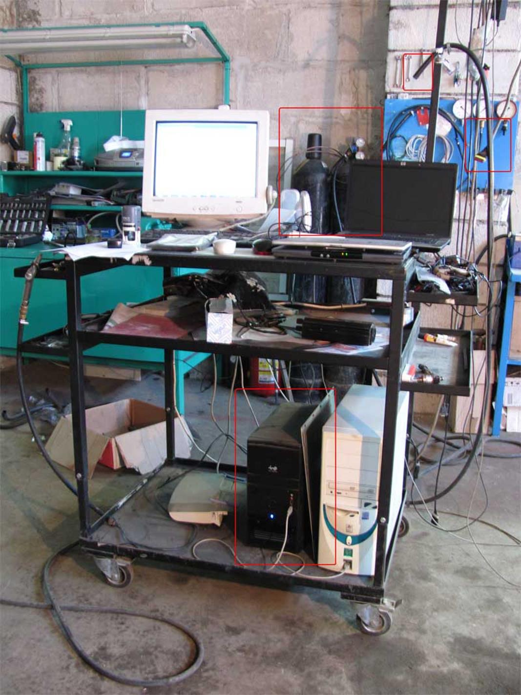
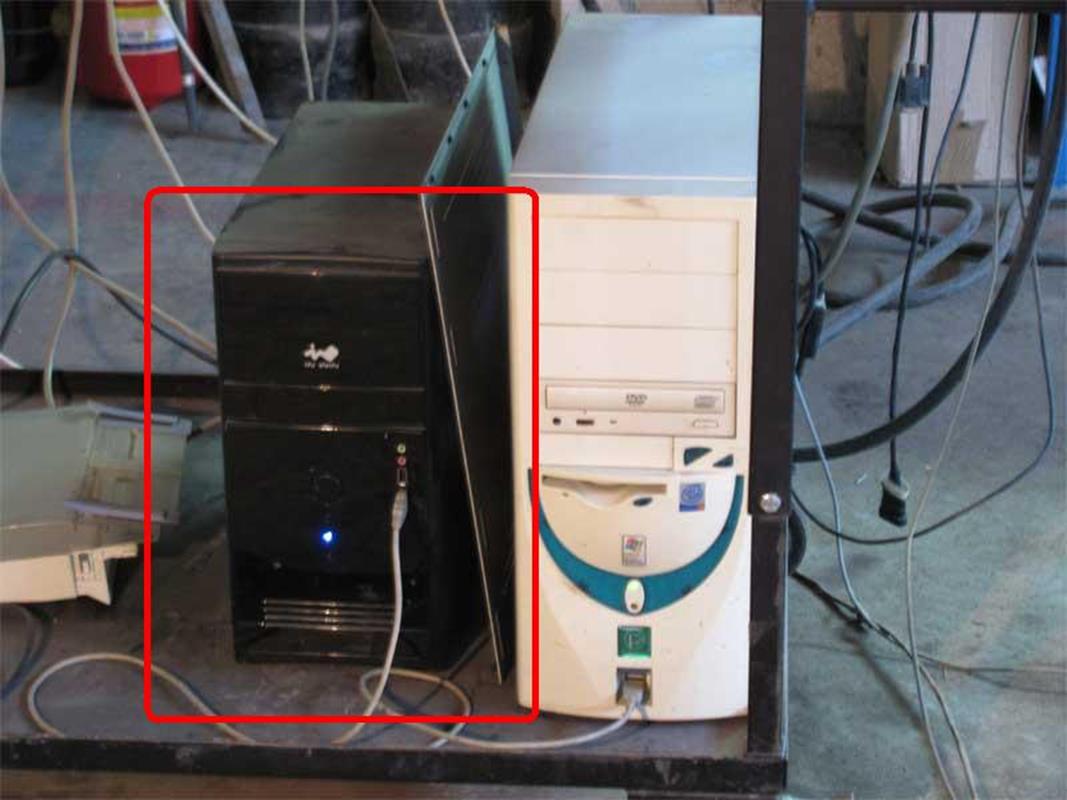
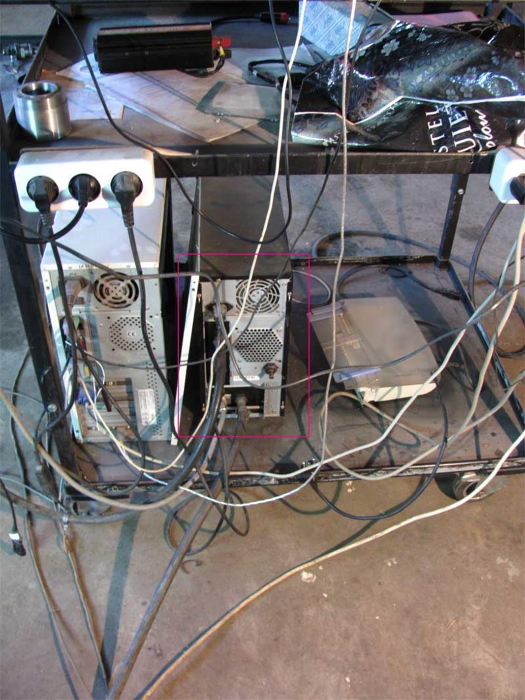
2. Test bench in use.
2.1. General view
2.2. Front view
2.3. Back view
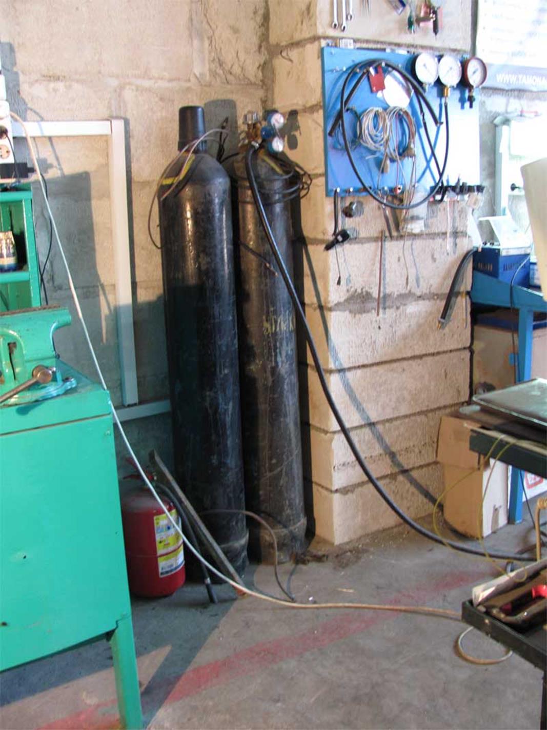
2.4. Bottles with
carbon dioxide
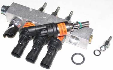
1. Space
adjustment in 4-inj. rail.
Screen video. High resolution,
sound.
Download video
(24.1Mb ) Watch video (YouTube)
E-mail: dze@bk.ru
Phone:
+375-293170994
Mikhail Dzahnidze